Vibration is inherent to compressors and different types of compressors each have their unique vibration signatures.
In this article, Ro-Flo Compressors takes a closer look at compressor vibration with the intent to help the reader understand what to expect with their compressor vibration.
Vibration Analysis
In order to determine if your compressor vibration is expected, you are going to need to perform some vibration analysis.
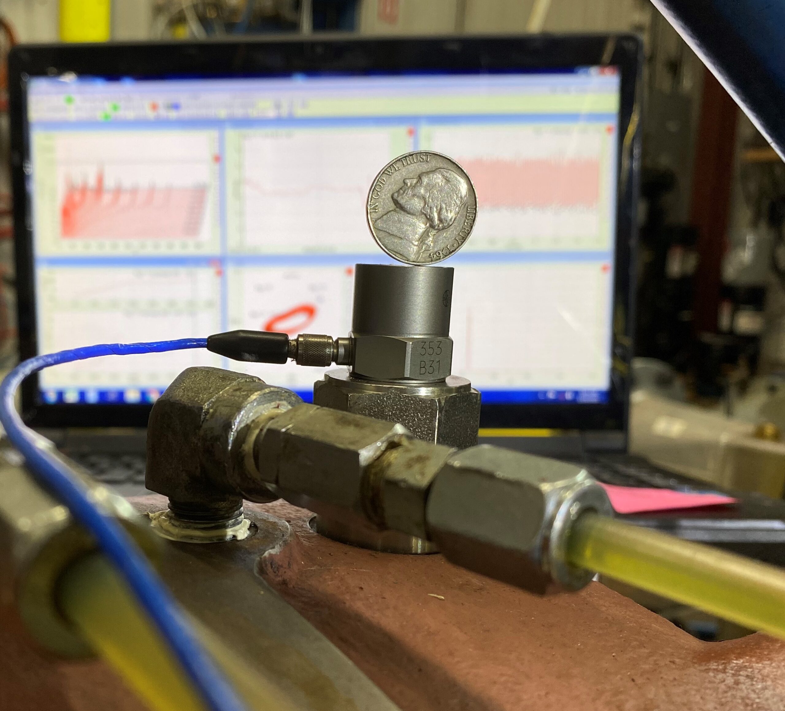
A very basic and simple means of vibration analysis is to stand a US nickel coin on edge on top of your compressor. If it rolls off, the compressor vibration is high. This is called the nickel test and although it has been reported to be useful for some, a more sophisticated vibration analysis approach is considered in the following.
Most vibration analyst’s and companies monitoring compressor vibration will measure vibration with instruments such as accelerometers, seismic probes and/or proximity probes. The data from these instruments are analyzed with a vibration tester/analyzer. Using a vibration tester/analyzer that has the ability to display data in spectrum plots and time wave form plots, will give users valuable insight to their compressor operation.
Spectrum Plots
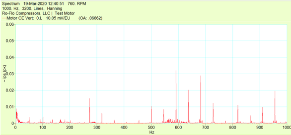
This article will primarily reference vibration data presented in spectrum plots. A spectrum plot shows vibration amplitude versus frequency. The spectrum plot shows what frequencies the vibration is occurring at i.e., what frequencies the compressor is vibrating at. Causes of compressor vibration have specific frequencies allowing them to be identified with the spectrum plot. The spectrum plot below shows vibration from an electric motor with a bearing fault.
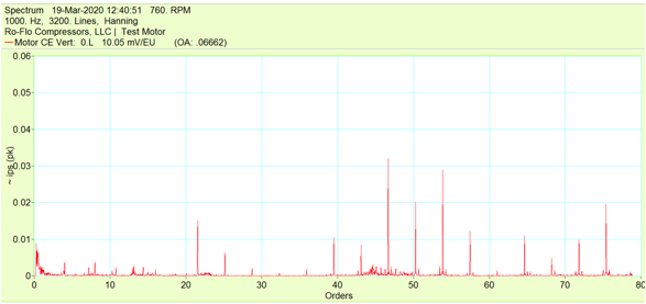
Another convenient way to display frequency on a spectrum plot is in orders. Orders is simply the vibration frequency divided by compressor operating speed frequency. For example, if a vibration amplitude is occurring at 60 hz and the compressor speed is 3600 rpm (60 hz), the order that the vibration amplitude is occurring at is 1, or 1X operating speed. Many causes of compressor vibration occur at frequencies that are directly proportional to the compressor operating speed, thus displaying frequency in orders on spectrum plots can be very beneficial. The plot below shows the same vibration data of the electric motor bearing fault, only the frequency axis is now in orders.
Common Causes of Compressor Vibration
Although each type of compressor will have a unique vibration signature, they can also have similar vibration behavior. Some of the common causes of compressor vibration that are not specific to any type of compressor are:
- Unbalance
- Misalignment
- Looseness
- Bearing Issues
- Resonance / Critical Speeds
There are many useful references readily available describing the above common causes of compressor vibration. It is important to understand what these issues look like in the vibration spectrum as well as compressor specific vibration behavior discussed as follows.
Centrifugal Compressor Vibration
Centrifugal (or dynamic) compressors use radial centrifugal action to force the flow from the suction to the discharge of the compressor. The increase in velocity of the process caused by this centrifugal action imparts kinetic energy which ultimately turns into pressure as it progresses to the discharge of the compressor. The following video from FS Elliot is a good example of how the centrifugal compressor operates:
How Does a Centrifugal Compressor Work? – YouTube
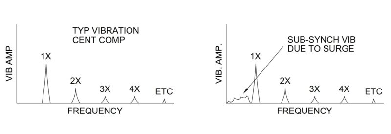
Compared to the other compressor technologies described in this article, centrifugal compressors are relatively smooth running in terms of vibration and normally have low vibration levels. A typical vibration spectrum from a centrifugal compressor will show the highest amplitude occurring at 1X running speed, with smaller amplitudes occurring at multiples of 1X. If notable vibration amplitudes are occurring at non-integer multiples of running speed, this may indicate an issue with the compressor.
Compressor Surge
One unique issue of centrifugal compressors is surge. Surge is when the compressor back pressure is too great, and momentary flow reversal or recirculation occurs inside the compressor. Surge will typically produce vibration amplitudes at frequencies below running speed (sub-synchronous). To avoid damaging a centrifugal compressor, it is not recommended to operate in surge or even near surge, and the conditions should be changed to avoid surge.
Positive Displacement Compressors
Positive displacement compressors rely on a mechanical volume reduction in order to transport and increase pressure of a gas. The remaining compressor types discussed in this article are all positive displacement compressors.
Reciprocating Compressor Vibration
Reciprocating compressors are positive displacement compressors that use pistons and cylinders like a car engine to compress gas. Gas is drawn into the cylinder and closed off from the suction. The volume of gas trapped in the cylinder is reduced by the piston, which increases the gas pressure. The cylinder then opens to the compressor discharge and allows the gas to leave the cylinder. The link immediately following provides an animation of a Howden reciprocating compressor:
Reciprocating Compressor C series – animation | Howden – YouTube
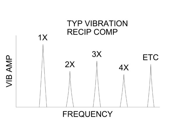
Also like a car engine, the reciprocating compressor has a crank shaft and connecting rods. Depending upon the design, reciprocating compressors can have mass unbalance forces due to opposed reciprocating components and moment / couple forces due to offsets of opposed reciprocating components. These forces are inherent to the compressor design and will cause vibration that occurs at frequencies of 1X and 2X running speed.
Pressure Pulsations
Another cause of reciprocating compressor vibration is due to pressure pulsations. Every time a cylinder opens and closes to the compressor suction and discharge, they create a pulse of pressure. A single acting cylinder will produce pressure pulsations at 1X running speed; whereas a double acting cylinder will produce pressure pulsations at 2X running speed. Pressure pulsations can be damaging, especially to piping, and they are usually managed with pulsation bottles.
The vibration spectrum will typically show amplitudes occurring at 1X running speed and many multiples of 1X running speed due to the above mentioned vibration. If measuring vibration near a crosshead, you can expect to see impacts from the valves, pulsations, etc. and they can excite resonances in the structure which results in changing amplitudes and frequencies throughout one revolution. In this case you may wish to analyze vibration in the time domain rather than a spectrum plot. Reciprocating compressors tend to have higher overall vibration levels than other compressors.
Screw Compressor Vibration
Screw compressors are also positive displacement compressors. Screw compressors have two (2) rotors, a male and female rotor. Typically, the male rotor is the driving rotor and it will have fewer lobes than the female rotor, a four (4) lobe male rotor with a six (6) lobe female rotor is common. Like reciprocating compressors, they reduce the volume of gas that is contained in the chambers between the rotor lobes and the walls of the compressor casing. As the rotors rotate, causing the rotor lobes to mesh, the chambers reduce in volume until reaching the discharge of the compressor. Mann Turbo provides a good screw compressor animation in the following video:
Screw Compressor Working Explanation by Animation with full detail – YouTube
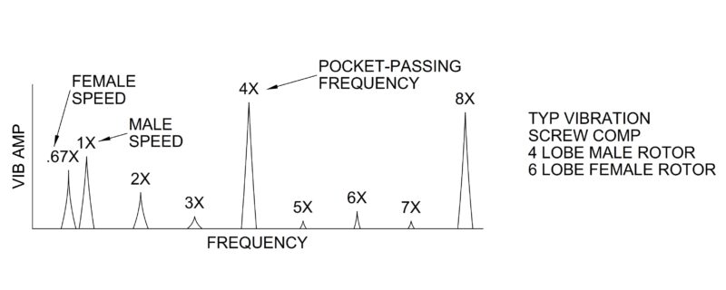
If the screw compressor male rotor has a different number of lobes than the female rotor, they will have different rotational speeds. Vibration can be expected to occur at 1X the male rotor speed and 1X the female rotor speed. Using the four (4) lobe male rotor / six (6) lobe female rotor example, the female rotor speed will be 4/6 = 0.67X the male rotor speed.
Pocket Passing Frequency
Like the reciprocating compressor, screw compressors also create pressure pulsations as a chamber opens and closes from the suction and discharge of the compressor. It is typical for these pressure pulsations to cause compressor vibration at the pulsating frequency and multiples of this frequency. For screw compressors, the pressure pulsation frequency is commonly referred to as the pocket passing frequency (PPF) and is equal to the running speed times the number of lobes on the rotor. Note that the male rotor speed times the number of male rotor lobes will be equal to the female rotor speed times the number of female rotor lobes – there is one (1) PPF for the compressor. And unlike reciprocating compressors, screw compressors can operate at higher speeds and generate more pressure pulsations in one revolution, thus it is common to see vibration at higher frequencies.
Although most screw compressors do not reach vibration amplitudes that are seen with reciprocating compressors, they are expected to be higher than those seen on centrifugal compressors. In fact, API recognizes this with a higher vibration design limit for screw compressors than for centrifugal compressors.
Liquid Ring Compressor Vibration
Like the reciprocating compressor and the screw compressor, liquid ring compressors are also positive displacement compressors. Liquid ring compressors have an impeller that is eccentric to the casing. A liquid sealing fluid is supplied into the compressor and the rotating impeller forces the liquid toward the outer diameter of the compressor casing, creating a liquid ring. As the impeller rotates through the sealing liquid, the volume between the impeller vanes reduces since the impeller is eccentric to the casing, which will compress the gas within the impeller. This can be seen visually in NASH’s video at the following link:
NASH Liquid Ring Pump – YouTube
Vane Pass Frequency
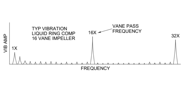
As expected with positive displacement compressors, the liquid ring compressor creates pressure pulsations. These pressure pulsations cause compressor vibration at a frequency equal to the operating speed times the number of vanes on the impeller. This frequency is known as the vane pass frequency. Vibration amplitudes occurring at multiples of the vane pass frequency can also be expected. Cavitation is a frequent concern with liquid ring compressors. If cavitation is occurring, it typically will cause an increase in vibration at the vane pass frequency and multiples of this frequency.
Liquid ring compressors can have lower vibration than other types of compressors. The liquid ring inside the compressor can dampen pressure pulsations, which helps keep vibration levels low.
Rotary Vane Compressor Vibration
The rotary vane compressor (or sliding vane compressor) is also a positive displacement compressor. Like the liquid ring compressor, the rotor of the rotary vane compressor is eccentric to the compressor casing. The rotor has slots cut into it where the compressor vanes reside. As the rotor spins, centrifugal force pushes the vanes out of the rotor slots and the vanes contact the cylinder bore. The volume contained between two (2) vanes will reduce as the rotor rotates and pushes the vanes back into their slots. The compression process is explained in detail in Ro-Flo’s compression cycle video.
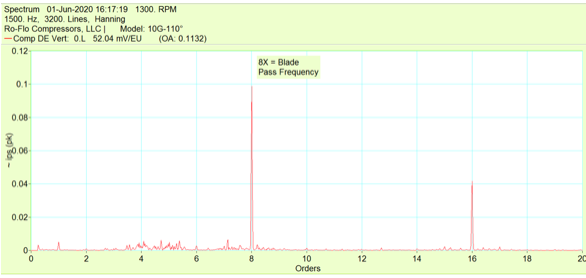
Blade Pass Frequency
The rotary vane also produces pressure pulsations since it is a positive displacement compressor. Typical and expected vibration in rotary vane compressors will occur at a frequency equal to the compressor operating speed times the number of vanes (or blades). This frequency is known as the vane pass frequency or blade pass frequency. For Ro-Flo Compressors, the blade pass frequency is typically equal to 8X running speed but can also be equal to 12X running speed. Vibration will also occur at multiples of the vane pass frequency. If the vibration spectrum is showing amplitudes occurring at frequencies not equal to vane pass or multiples of vane pass, this may be indicative of an issue with the compressor or system. For example, a stuck vane or blade within the compressor may show high levels of 1X, 2X, 3X, etc…
Vibration Monitoring
Similar to other compressors, the best method of using vibration data to assess Ro-Flo Compressor performance is to measure vibration data soon after commissioning equipment and reaching normal steady state operating conditions. This measured vibration data can be used as a baseline to compare to future vibration measurements. Comparisons should not only include overall vibration amplitudes, but also spectrum data showing amplitude vs. frequency. Note that changes in operating conditions such as speed, pressure and temperature all have an effect on the compressor vibration, thus it is also important to include the operating conditions as part of the vibration data.
Learn More with Ro-Flo Compressors
Do you have questions about your compressor vibration? Would you like an in-depth vibration analysis done on your compressor?
Ro-Flo Compressors’ state-of-the-art test facility, Rotary Test Center, utilizes the latest technologies in vibration measurement and analysis. Allow the experts at Ro-Flo Compressors to perform a complete vibration analysis on your compressor. Contact our team today to get started.